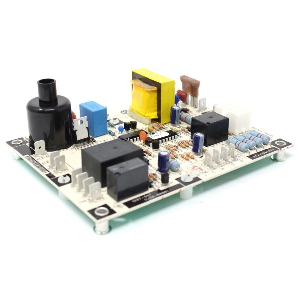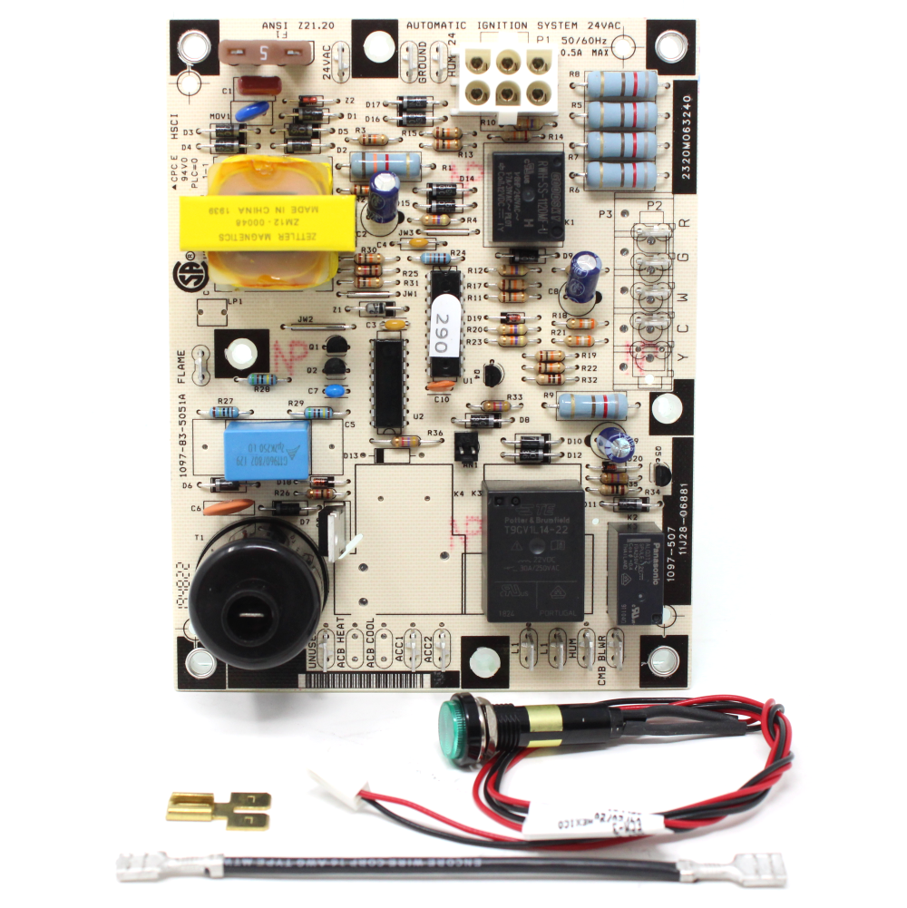
Heil 11J28-06881 OEM Unit Heater Control Board – Replacement for J28R06881.
Product Overview
The Heil 11J28-06881 Control Board is the official OEM replacement for the outdated J28R06881 board, designed to ensure safe, consistent operation of Heil unit heaters. This updated board is tailored for heating-only systems, eliminating unnecessary cooling relays while introducing a new LED diagnostic wire for easier troubleshooting.
Whether you’re servicing a garage heater, maintaining a commercial HVAC unit, or restoring performance in your Heil heater, this board delivers durability and efficiency.
Features & Benefits
-
OEM Replacement: Built to Heil’s specifications to replace the discontinued J28R06881 board.
-
Heating-Specific Design: Cooling relay removed to simplify operation in unit heaters.
-
LED Diagnostic Upgrade: Includes a 20” wire for internal or external mounting to ease service checks.
-
Streamlined Wiring: Fan motor wires now land on ACC1 terminals; no jumper required.
-
Reliable Performance: Ensures safe ignition and efficient operation for Heil unit heaters.
Specifications
-
Part Number: 11J28-06881 (Replaces J28R06881, 11J28R06881)
-
Compatible Heil Series: Heating-only Heil unit heaters (consult model chart for match)
-
LED Wire: 20” with lock nut for secure mounting
-
Terminals: ACC1 fan connections replace outdated jumper system
-
Function: Designed exclusively for heating mode
Installation Tips
-
Shut off power before installation.
-
Connect fan wires to ACC1 terminals—jumper no longer needed.
-
Mount LED externally (11/16” hole required) for easier viewing, or position internally away from burner.
-
Follow Heil service recommendations for best results.
FAQs
Q: Can this replace the J28R06881 board?
A: Yes, it is the direct OEM Heil replacement.
Q: Why is there no cooling relay?
A: Heil unit heaters operate only in heating mode, so the relay was unnecessary.
Q: How does the diagnostic LED work?
A: The LED connects to the control board and provides fault codes for faster troubleshooting.
Your payment information is processed securely. We do not store credit card details nor have access to your credit card information.


